Thursday, May 19, 2016

MikroTik | Beginner

Step 1: Connect your Mikrotik router with your pc with a utp cable. Collect winbox software (or download it from www.mikrotik.com), click on refresh tab for MAC scan, select the mac which has shown, login with admin user, no password.

Step 2: Add wan side IP address, subnet mask and select port.


Step 3: Then add LAN Side IP address, subnet mask and select port.

Step 4: Add routes.

Step 5: Add routes.

Step 6: Add DNS address.

Step 7: Add NAT rule.

Step 8: Add NAT rule.


Step 9: Add NAT rule.

Step 10: Add different user name and password. Might be set password for admin user account.

Explanation: First we give a code snippet and then explain what it actually does.

/ip address
add address=103.195.0.138/24 comment="Internet" interface=ether1 network=\
192.168.170.0
add address=192.168.0.1/24 comment=LAN interface=bridge1 network=192.168.0.0

/ip route
add check-gateway=ping distance=1 gateway=103.195.0.136

/ip dns
set servers=8.8.8.8, 4.2.2.2

/ip firewall nat
add action=masquerade chain=srcnat src-address=192.168.0.0/24

END

Wednesday, May 18, 2016

MikroTik | PC Based Mikrotik IOS Install

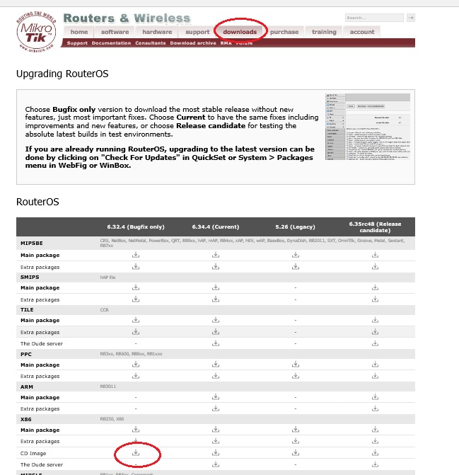
Step 1: Go to www.mikrotik.com click on Download, Select your Motherboard (If it is not Intel original or AMD then you should select Other x86), Now Download ISO image, You will also download winbox for remote administration from right side:


Step 2: Install procedure: After write your CD, boot from CD ROM (select BIOS 1st boot setting CDROM). press “a” for select all package, then select “i” for install, Press y, y. That’s all, Install will be completed.


Step 3: Start Configuration: Connect your Mikrotik Router with your PC with a UTP cable.

Step 4: Collect Winbox software (or download it from www.mikrotik.com), Click on MAC scan, select the mac which has shown, login with admin user, no password.


END

Wednesday, May 4, 2016

Mikrotik | GRE (Generic Routing Encapsulation) Tunnel

GRE (Generic Routing Encapsulation) is a tunnelling protocol that was originally developed by Cisco. It can encapsulate a wide variety of protocols creating a virtual point-to-point link.

GRE is the same as IPIP and EoIP which were originally developed as stateless tunnels. Which means that if the remote end of the tunnel goes down, all traffic that was routed over the tunnels will gets blackholed. To solve this problem, RouterOS have added 'keepalive' feature for GRE tunnels. GRE tunnel adds a 24 byte overhead (4-byte gre header + 20-byte IP header).

Example uses
• In conjunction with PPTP to create VPNs.
• In conjunction with IPsec VPNs to allow passing of routing information between connected networks.
• In Mobility protocols.
• In A8/A10 interfaces to encapsulate IP data to/from Packet Control Function (PCF).
• Linux and BSD can establish ad-hoc IP over GRE tunnels which are interoperable with Cisco equipment.
• Distributed denial of service (DDoS) protected appliance to an unprotected endpoint.


Step 1: Login the Mikrotik router using winbox and done the necessary configuration like set ip address (wan & local), dns, nat and dhcp server (if dhcp is required) etc.
Step 2: After completing the necessary configuration, follow the below screenshot for example (For first mikrotik router).


Step 3: The below screenshot is ip information of Mikrotik (For first mikrotik router).


Step 4: Add the static router to reach the remote side local ip address (For first mikrotik router).


Step 5: After completing the necessary configuration, follow the below screenshot for example (For second mikrotik router)..
Step 6: The below screenshot is ip information of Mikrotik (For second mikrotik router).


 Step 7: Add the static router to reach the remote side local ip address (For second mikrotik router).

Explanation: Let's assume this configuration.
For first mikrotik router:
 /system identity
set name=MikroTik_1


/ip address
add address=182._._.52/27 comment="Public IP" interface=ether1 network=\
    182._._.32
add address=192.168.20.1/24 comment=Local interface=Bridge_Lan network=\
    192.168.20.0
add address=172.16.1.1/30 comment="P2P IP" interface=\
    gre-tunnel_with_Mikrotik_1 network=172.16.1.0


/interface gre
add !keepalive local-address=182._._.52 name=gre-tunnel_with_Mikrotik_1 \
    remote-address=122._._.35


/ip route
add distance=1 gateway=182._._.33
add distance=1 dst-address=192.168.21.0/24 gateway=172.16.1.2

For second mikrotik router:

/system identity
set name=MikroTik_2


/ip address
add address=122._._.35/27 comment="Public IP" interface=ether1 network=\
    122._._.32
add address=10.1.1.1/24 comment=Local interface=Bridge_Lan network=10.1.1.0
add address=192.168.21.1/24 comment=Local interface=ether4 network=\
    192.168.21.0
add address=172.16.1.2/30 comment=P2P interface=gre-tunnel_with_Mikrotik_2 \
    network=172.16.1.0


/interface gre
add !keepalive local-address=122._._.35 name=gre-tunnel_with_Mikrotik_2 \
    remote-address=182._._.52


/ip route
add distance=1 gateway=122._._.33
add distance=1 dst-address=192.168.20.0/24 gateway=172.16.1.1


Thank You

MikroTik | Load Balancing | Per Connection Classifier Method

PCC matcher will allow you to divide traffic into equal streams with ability to keep packets with specific set of options in one particular stream (you can specify this set of options from src-address, src-port, dst-address, dst-port)


Step 1: Login Mikrotik router.

Step 2: Add both ISP IP address in Mikrotik Address list.

Steps 3: Go to mangle and create mangle rules.

Steps 4: Then go to nat and create nat rules.


Steps 5: Go to routes and create routes rules.

Steps 6: Finally configure is done.

Explanation: Let's assume this configuration.

/ip address
add address=192.168.170.18/24 comment=ISP_01 interface=ether1 network=192.168.170.0
add address=172.16.1.2/30 comment=ISP_02 interface=ether2 network=172.16.1.0
add address=192.168.0.1/24 comment=Local interface=ether3 network=192.168.0.0

Policy routing:

/ip firewall mangle
add chain=input dst-address=192.168.170.0/24
add chain=input dst-address=172.16.0.0/30


add action=mark-connection chain=prerouting connection-mark=no-mark \ in-interface=ether1 new-connection-mark=ISP_01_IN
add action=mark-connection chain=prerouting connection-mark=no-mark \ in-interface=ether2 new-connection-mark=ISP_02_IN

add action=mark-connection chain=prerouting connection-mark=no-mark \ dst-address-type=!local in-interface=ether3 new-connection-mark=ISP_01_IN \ per-connection-classifier=src-address:2/0
add action=mark-connection chain=prerouting connection-mark=no-mark \ dst-address-type=!local in-interface=ether3 new-connection-mark=ISP_02_IN \ per-connection-classifier=src-address:2/1

add action=mark-routing chain=prerouting connection-mark=ISP_01_IN \ in-interface=ether3 new-routing-mark=ISP_01_OUT passthrough=no
add action=mark-routing chain=prerouting connection-mark=ISP_02_IN \ in-interface=ether3 new-routing-mark=ISP_02_OUT passthrough=no

add action=mark-routing chain=output connection-mark=ISP_01_IN \ new-routing-mark=ISP_01_OUT
add action=mark-routing chain=output connection-mark=ISP_02_IN \ new-routing-mark=ISP_02_OUT


Nating rule:

/ip firewall nat
add action=masquerade chain=srcnat out-interface=ether1
add action=masquerade chain=srcnat out-interface=ether2

Routing

/ip route
add check-gateway=ping distance=1 gateway=192.168.170.254 routing-mark=ISP_01_OUT
add check-gateway=ping distance=2 gateway=172.16.1.1 routing-mark=ISP_02_OUT
add check-gateway=ping distance=1 gateway=172.16.1.1,192.168.170.254

END

MikroTik | Load Balancing | Equal Cost Multi-Path Method

This example is improved (different) version of round-robin load balancing example. It adds persistent user sessions, i.e. a particular user would use the same source IP address for all outgoing connections. Consider the following network layout:


Step 1: Login Mikrotik router.

Step 2: Add both ISP IP address in Mikrotik Address list.


Step 3: Go to mangle and create mangle rules.


Step 4: Then go to nat and create nat rules.


Step 5: Go to routes and create routes rules.


Step 6: Finally configure is done.


Explanation: First we give a code snippet and then explain what it actually does.

/ip address
add address=192.168.170.18/24 comment=ISP_01 interface=ether1 network=192.168.170.0
add address=172.16.1.2/30 comment=ISP_02 interface=ether2 network=172.16.1.0
add address=192.168.0.1/24 comment=Local interface=ether3 network=192.168.0.0

Connections to the router itself:

/ip firewall mangle
add action=mark-connection chain=input in-interface=ether1 \ new-connection-mark=ISP_01_IN
add action=mark-connection chain=input in-interface=ether2 \ new-connection-mark=ISP_02_IN
add action=mark-routing chain=output connection-mark=ISP_01_IN \ new-routing-mark=ISP_01_OUT
add action=mark-routing chain=output connection-mark=ISP_02_IN \ new-routing-mark=ISP_02_OUT

Nating rule:

/ip firewall nat
add action=masquerade chain=srcnat out-interface=ether1
add action=masquerade chain=srcnat out-interface=ether2


Routing:

/ip route
add check-gateway=ping distance=1 gateway=192.168.170.254 routing-mark=ISP_01_OUT
add check-gateway=ping distance=2 gateway=172.16.1.1 routing-mark=ISP_02_OUT
add check-gateway=ping distance=1 gateway=172.16.1.1,192.168.170.254

END